Ford Laser Hotwiring
August 2011
Background
After a respectable gentleman tried to break into my friend's car and turn the ignition with a screwdriver (unsucessfully), my friend was left with an unworking ignition.
He still needed the car, and until he could get the ignition replaced we decided to try hotwiring the car.
Disclaimer
Hotwiring a car is a bit of a grey area. It's perfectly legal to do - assuming you own the car - but the same instructions I provide here could be used nefariously. That being said, I find it unlikely that someone trying to steal a car is going to be able to sit down with the ignition cover off, a soldering iron in hand and wires going everywhere for 45 minutes while they get it all sorted out.
These instructions are for purely reference purpose, and I take no responsibility for any damage you do to your car.
Materials
- Wire
- 2x Rocker Switches (I used these)
- 1x Push Button (I used this one)
- Heatshrink
- Solder
- Soldering iron
- Screwdriver (Phillips head)
Details
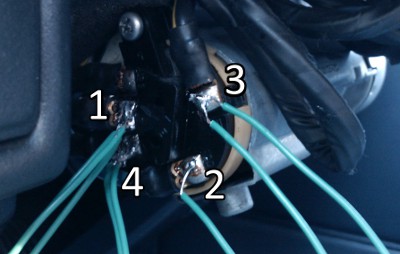
Hotwiring the car requires four seperate contacts, all of which are readily accessible from the back of the ignition jack for the key. Getting access to these is the first step.
Take your screwdriver and remove the four screws that hold the plastic ignition cover in place. Once that's done, the four required contacts are numbered below.
- +12V
- Accessory
- On
- Engine crank
These are the different settings your key goes to when it's in the ignition. First to accessory, then to "on", then finally a momentary contact with the engine crank to get the motor started.
By connecting each contact successively to the +12V rail, you get the same effect as having the key in that position.
So the first step is to solder the wires to the contacts on the ignition. You'll notice that there are different numbers of wires on each contact. This is due to the differing current (Amps) requirements for each setting. The wire I was using was good for 2A continuous per strand. Using a multimeter I found that the accessory line was using 400mA, the "on" line using 2.5A, so the accessory line only needed one strand, while the "on" line needed two.
Wire the switches up according to the schematic to the right (remembering to use multiple wires where necessary), and check each switch works as you complete them.
With all the switches in place, it should just be a simple matter of turning the accessory line on, the "on" line on, and then finally pressing the engine crank button and the car should start. When you've arrived at your destination just turn the "on" switch back off, and the car should stop.
Future work
This was only a very temporary "fix" to a situation, so the simplest possible method was used - if you had a bit more time, and didn't mind the concept of having an electronic ignition system there could be some very interesting possibilities. Some that came to mind were:
- Re-implementation of a keyless ignition system using RFID
- Using a keypad to enter a code to start the car
- Interfacing a bluetooth module to communicate with your phone
- Connecting a gamepad and requiring a "cheatcode" to be entered to start the car
Of course, there are inherent security risks with having a system like this in place, so once a replacement ignition was found it was installed and the switches and wires were removed.