Digital bar fridge thermostat
March 2009
Sitting around one warm summer's night drinking some excellent homebrew beer with some mates, we had been playing around with the idea of building a kegerator-type thing to serve ice cold beer on demand.
We thought that an Esky, some copper piping and valve attachments along with some ice would probably be all it'd take, however after looking online at reasonably sized cooler boxes we noticed the cost was prohibitive (at least, when you're on a student's budget).
So the project took a back seat, until a few weeks later driving home from a party late one Saturday night we saw a bar fridge on the side of the road. I immediately thought that it'd be a perfect substitute for the cooler box in our project, and with a bit of shuffling, the solution to our problem was in the car!
However, it was the next morning that we discovered that unfortunately, the fridge actually worked... Unwilling to dismantle a perfectly working bar fridge, we re-targeted our project. Not too long ago we'd brewed a James Squire Golden Ale imitation, which had been exposed to some unsavoury weather conditions (read: Australian summer) and could have probably been better if it hadn't spent time at 45-50 degrees Celcius. A fridge would have been a good solution to this problem!
However, the built-in thermostat would only allow the fridge to go up to a maximum of 5 degrees... hardly an ideal beer brewing temperature. After looking online for replacement thermostats and finding them both hard to come by, and quite expensive, I decided to design my own.
I needed something that could switch the compressor of the fridge on and off depending on the temperature inside the fridge. Switching mains power on and off meant that I'd need a relay, and I remembered seeing a good tutorial over at Sparkfun explaining the ins and outs of what is needed.For more information I highly recommend reading the article.
I wanted the thermostat to conform to a couple design requirements:
- Have a simple, small design
- Be reasonably power efficient
- Have an adjustable temperature setting
I will explain how these have influenced my decisions below.
Power
I needed to solve the problem of how to power the thermostat. I could have designed an AC-DC rectifier and piggy-backed the power from the fridge itself. This method would have also required a DC-DC step down converter, but it would have significantly increased the number of parts that I needed to build the overall project, increasing the complexity and physical size of the overall device.
One alternative was to use a battery pack and a 7805 linear voltage regulator to supply a nice 5V to the rest of the system. This certainly fulfilled the criterion of being small and simple, but it wasn't without its caveats. Firstly a 4xAA battery pack only delivers ~6V, and a 7805 LVR technically requires at least 7.2V to produce a 5V output according to the datasheet. The other issue is that the batteries will run out eventually have will have to be replaced. The first problem proved to be a non-issue as the 7805 still pumped out 4.88V from a 6V supply, probably enough for most ICs. I decided that this would be a fine solution, despite the flaws.
Temperature controlled switching
So that solved the problem of power, and the actual turning on and off of the fridge, but I still needed some kind of device which would be able to send a signal to the relay setup when the temperature exceeded a preset amount.
I opted to use a thermistor for temperature detection. These things are basically resistors which change resistance depending on the ambient temperature, in my design I chose to use a 10k NTC thermistor. This means that the resistance at 25 degrees Celcius would be 10 kOhms, and decrease in resistance as it got hotter. From the datasheet of the component I found that at 18 degrees the resistance would be approximately 13 kOhms. In retrospect, I feel that I should have purchased a 50kOhm thermistor, as this would have reduced the current flowing through it and lowered the overall power consumption.
I used the thermistor in conjunction with another resistor to create a simple voltage divider network, to give a varying voltage depending on the ambient temperature. That voltage could then be measured by some IC and compared to a reference voltage. My first thought was that a comparator would be an elegant solution, however after ordering a low-power comparator I found that it required a 2V difference between the two inputs for it to switch. This was completely impractical as a 2V difference translated to a 47 degree temperature change. So this ruled out the comparator, and instead I ordered a ATTiny25 Atmel microcontroller, which has a couple of ADC ports which can read the voltage on any of the ADC pins to an accuracy of 10 bits. This meant that I needed to write some firmware for the AVR to do the comparison but being reasonably familiar with the process this didn't really bother me.
So putting all this together got me a circuit that looked something like this:
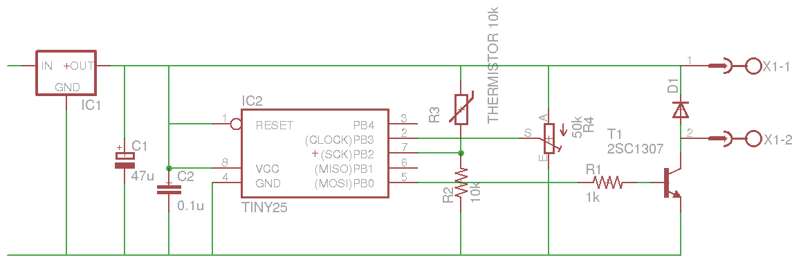
Hardware
Materials:
- 7805 Linear voltage regulator ($0.25 Futurlec)
- 8-pin IC socket ($0.04 Futurlec)
- Atmel ATTiny25 microcontroller ($1.40 Futurlec)
- 50k trimpot ($0.15 Futurlec)
- 0.1uF ceramic capacitor ($0.10 Futurlec)
- 47uF electrolytic capacitor ($0.07 Futurlec)
- 10k NTC thermistor (alt. 50k NTC thermistor) ($0.35 Futurlec)
- 10k Ohm resistor (alt. 50kOhm resistor) ($0.20 Futurlec)
- 1k Ohm resistor ($0.20 Futurlec)
- 1N4001 general purpose diode ($0.20 Futurlec)
- MPS2222A general purpose NPN transistor ($0.50 Futurlec)
- Solid state relay (Current rating depends on device being switched) ($4.95-$24.90 Futurlec)
- 2 terminal 5mm spaced terminal block (optional) ($0.40 Futurlec)
- 4xAA battery holder ($0.40 Futurlec)
- 9V battery clip ($0.10 Futurlec)
- Small stripboard ($0.95 Futurlec)
All up this comes to $5.31, plus the cost of your relay, plus a few extra dollars for postage, you should be looking at a total cost of $15-20. (All prices are USD)
Alternatively you could omit the stripboard and go about making or ordering a PCB, using the eagle BRD files that I've included on the final page. Keep in mind however that while I assume it will work, I haven't actually produced a PCB from the design, so anything could happen.
Solder it all up together, and you should have something that looks along the lines of this:
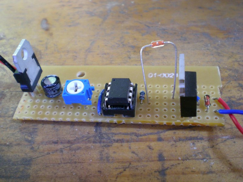
Notice that the thermistor has been mounted high off the stripboard, this is just to minimise the effect of any ambient heat that is being generated by either the AVR or the transistor.
You might notice I've omitted the 0.1uF decoupling capacitor in this photo, which is a bit of a no-no especially in an environment where a load is being switched - but rest assured it's been placed in just next to the AVR now.
Software
So now that the hardware side of things is all worked out it's time to get started on programming the ATTiny.
It will be serving a pretty basic purpose, compare the voltage at pin 7 (thermistor/resistor network) with the voltage at pin 2 (potentiometer output), then determine whether to switch the transistor on or not based on the values of the two ADC inputs. I won't go into too much detail about the code, as it's commented, but I'll mention a couple of points of interest.
Firstly, the use of interrupts. By using interrupts for the ADC reading, it allows the processor to go to sleep while waiting for the ADC to finish it's conversion reducing the amount of power consumed by the AVR in this period. I have also set the frequency of the ADC to the lowest possible setting, as it doesn't really need to be taking samples too often, which reduces the power used by the ADC, as well as increasing the time the processor spends asleep.
Secondly, you'll notice that I mention hysteresis in the code. Wikipedia has a good article on hysteresis, but in essence it is where a difference between the "switch-on" threshold and the "switch-off" threshold. The reason that I've put this in here is to avoid rapidly turning the relay on and off which would put the compressor of the fridge under a bit of stress.
Once the code is written and built, the firmware needs to be flashed to the device itself. For this I used avrdude, a great little program which can send the neccessary data to a AVR programmer. The AVR programmer I use is ladyada's fantastic USBtinyISP. It can be purchased in kit form from her website. You can use any other programmer, but remember to edit the Makefile in the source to reflect the changes.
The thermostat has been installed in the fridge, and been left on and the temperature monitored. The trimpot needed to be adjusted once, but the fridge sits at a pretty constant 18 degrees now. I'm not sure how long the batteries will last, but measuring the current draw from the device while the relay was active showed that it drew 80uA. The AA batteries will supply ~1500mAh, and a quick bit of calculation yields 18750 hours (a bit over two years). Now, I think that's a pretty generous estimate, as the batteries probably won't like being kept chilled, but it'd be safe to assume you'd be able to get through a brew or two with one set of batteries.
I've uploaded the source for the AVR firmware and the eagle schematics/board files here.
The source is licensed under the GPLv3, and the eagle files are licenced under the Creative Commons Attribution-Share Alike 2.5 Australia License, which can be found in their respective archives.
If anyone has any question or comments feel free to drop me a line at [email protected] and I'll be sure to get back to you.