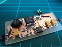
Switchmode supply
October 2011

About
This is a sneak preview of a small section of a much larger project I'm working on. It's a power regulation circuit based around the Linear LT1370 switching regulator.
I decided to try my hand at etching a circuit using the toner-transfer method and my results weren't bad - certainly good enough for my needs (after I'd worked some kinks out).
Element 14 were kind enough to sponsor most of the components used in this prototype as a part of their community development program, so many thanks to them! Check out their community page for discussion forums, blogs, and the ever popular Ben Heck show!
Components
Prices in AUD, at time of writing (16/10/2011)
- 1x Linear LT1370 switchmode regulator ($14.71)
- 3x AVX TPSD Series 100uF Tantalum Caps ($3.54)
- 1x 18.7kOhm 0603 Resistor ($0.008)
- 1x 6.19kOhm 0603 Resistor ($0.008)
- 1x 2kOhm 0603 Resistor ($0.03)
- 1x 4.7nF 0603 Capacitor ($0.01)
- 1x 47nF 0603 Capacitor ($0.014)
- 1x 10uH SMD Inductor ($1.62)
- 1x MBRD835L Shottky Diode ($1.02)
- 1x TPS730285 LDO ($0.488)
- 1x 100nF 0603 Capacitor ($0.02)
- 1x 2.2uF 0603 Capacitor ($0.064)
Printed Circuit Board
The circuit board for this particular project was actually etched at home. I had never actually tried this before, mainly because of the cost-effective alternative of getting a batch made up professionally by the folks at seeedstudio. However, for this particular project, timeliness was a factor as I wanted to get prototyping straight away and not have to wait for the boards.
I used the toner transfer method, printing out the design onto glossy magazine paper then using a clothes iron to stick the etch resist to the copper. This worked reasonably well, although I did end up using a fairly generous track clearance of 12mil in Eagle.
The first board I etched was mirrored because I had flipped the board both horizontally and vertically (only do one of these apparently). A comparison of the boards shows the benefits of increasing the track clearance, and the increased quality of the board by being a bit more careful in the transfer process (although there were still some issues with the 2nd board).
Unfortnately the design had to be single layered, and I needed to use some jumper wires to tie all the ground planes together, but the final circuit worked beatifully, despite the ugly wires on the board.
Notes
Artline Ergoline permanent markers are not etch resistant, so my attempts at fixing up the second board were in vain.
The device performs exceptionally well, outputting 5.05V with very slight noise with a medium load - not bad for a switchmode supply.
Further testing with regard to the current output capabilities and the possibility of using smaller tantalum capacitors (like these ones) is being undertaken.